
General Purpose Current to Pressure I/P Converter
Regular price
$1,562.53
Excl GST: $1,420.48
Excl GST: $1,420.48
Taxes included.
Shipping calculated at checkout.
SKU :
SKU:IP210A-IP210
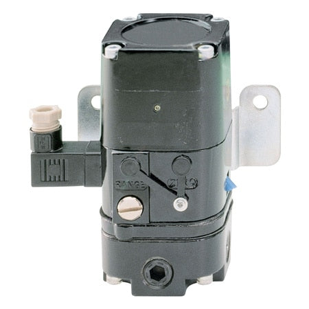
The IP210A series is a general purpose pressure converter with a IP65/NEMA 4 enclosure for pneumatic control up to 120 psi with a DIN connection and adjustable zero and span.
Couldn't load pickup availability
- Description
- Download Brochures
A “current to pressure” (I/P) converter converts an analog signal (4 to 20 mA) to a proportional linear pneumatic output (3 to 15 psig). Its purpose is to translate the analog output from a control system into a precise, repeatable pressure value to control pneumatic actuators/operators, pneumatic valves, dampers, vanes, etc. Both IP210 and IP210A are loop-powered instrument, which eliminates the need for an external power supply (except for IP210-X120).
Principle of Operation
OMEGA's IP210 and IP210A converts an analog signal (4 to 20 mA) to a proportional linear pneumatic output (3 to 15 psig). Its uncomplicated design and proven electromagnetic force balance deliver consistently high performance.
Both series provides a reliable, repeatable, accurate means of converting an electrical signal into pneumatic pressure. Its force balance principle is a coil suspended in a magnetic field on a flexible mount. At the lower end of the coil is a flapper valve that operates against a precision ground nozzle to create a backpressure on the servo diaphragm of a booster relay.
The input current flows in the coil and produces a force between the coil and the flapper valve, which controls the servo pressure and the output pressure.
Zero adjustment of the unit is made by turning a screw that regulates the distance between the flapper valve and the air nozzle. Span adjustment is made by varying a potentiometer, which shunts input current past the coil. An integral volume flow booster provides adequate flow capacity, resulting in fast response time and accurate control.
×

- Choosing a selection results in a full page refresh.
- Opens in a new window.